Building the Mite
A rover from scratch for learning SLAM and robot AI
This is my first post about the Mite project and my first blog entry about a robot, so I’ll begin with some background.
Backstory
I’ve been fascinated with robots for as long as I can remember, and I have been building robots since I was a kid. I had Lego Mindstorms and competed in the FIRST Lego League. I got a Parallax BOEbot kit and programmed it to do all sorts of things in BASIC. In college, I repurposed the chassis to add a CMU Cam module and an ultrasonic distance sensor on a pan/tilt assembly, controlling the whole thing with a Raspberry Pi. At some point, that robot was disassembled and rebuilt into a simpler, remote-controlled robot with a claw—a one-day project to prepare a STEM demo for children visiting the university for a science fair.
My robot projects effectively paused until around 2022, when my father and I started building a new robot with a 3D printed frame and four independently controlled wheels, LIDAR, RADAR, a camera with pan/tilt and incredible optical zoom, and a whole lot more. Unfortunately, that robot project is on hold pending some design challenges, and I started this project so I could work on the software elements in the meantime. That other robot will be posted here eventually.
The Plan
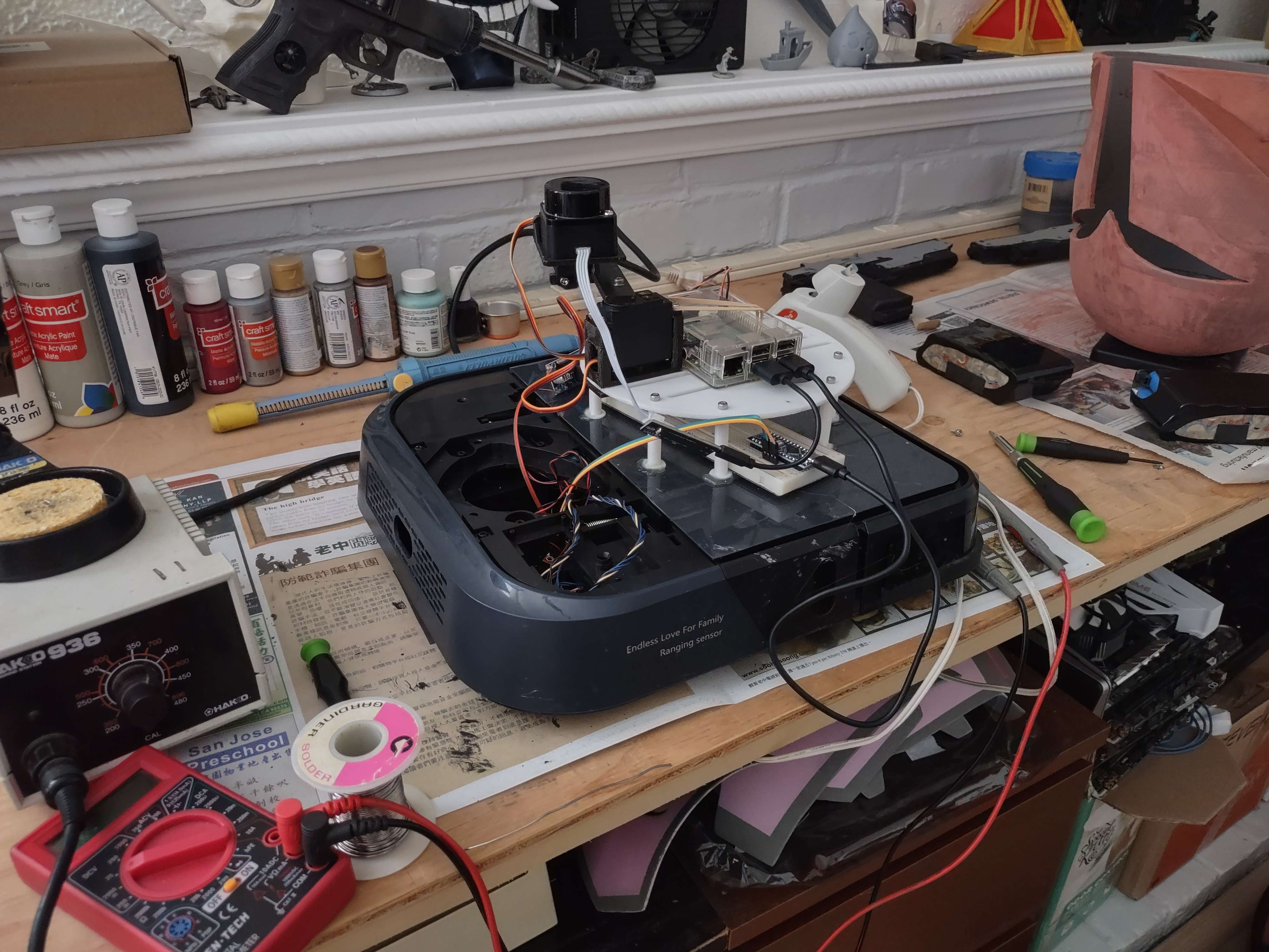
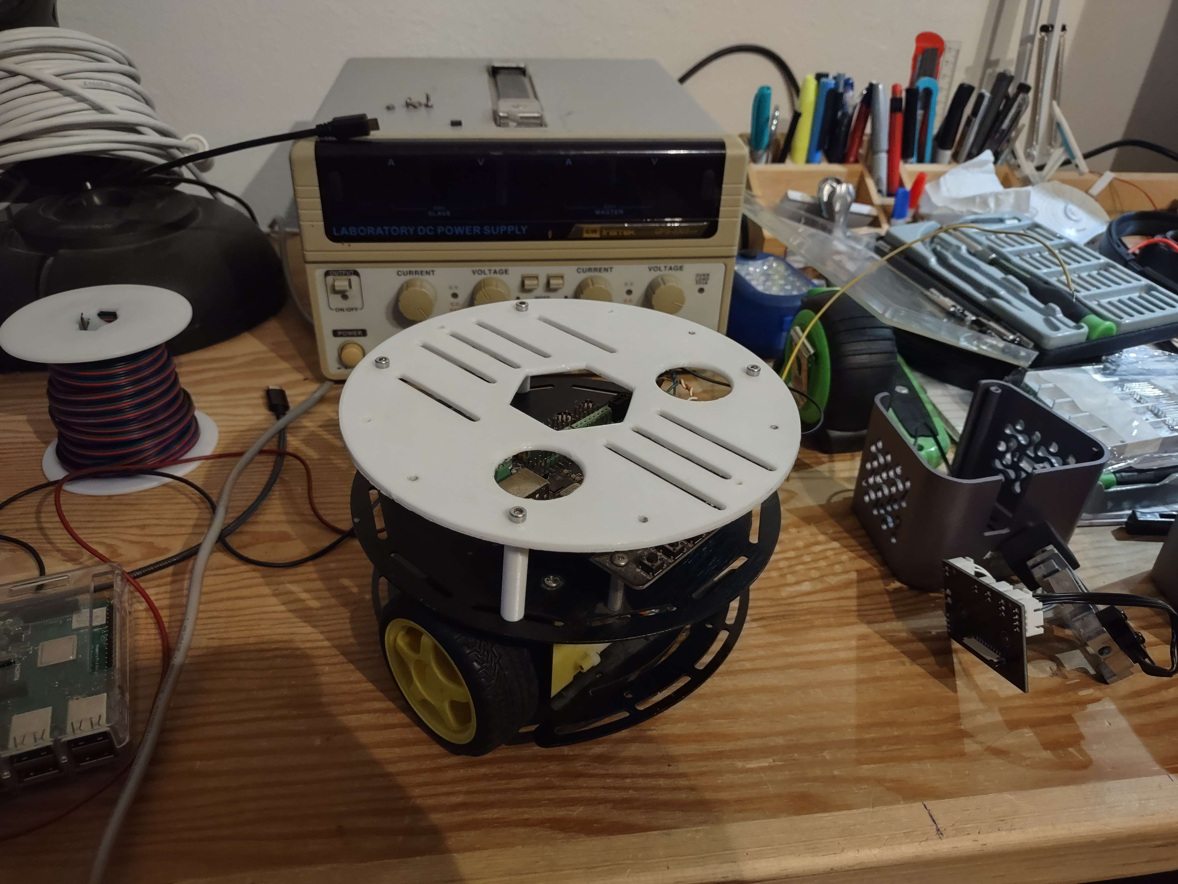
I named it Mite because my objective was to make a minimal, compact robot with simple mechanics to serve as a test bed for the software and AI I want to prototype. This meant starting with an old generic 2WD robot kit I’d had laying around since college. It is the ubiquitous round 2WD turtle-style chassis made from black sheet metal, yellow wheels, and yellow gear motors. The kit as I found it featured a Romeo control board, which is basically an old-fashioned Arduino Uno clone with convenient headers for servos and analog sensors as well as a full H-bridge. A little time in FreeCAD and I had a 3D printed upper deck to mount everything on.
From here, I started making a plan for the hardware and software.
Hardware:
- 2WD turtle chassis
- Romeo board for DC motor and servo control
- Raspberry Pi handling communications and sensors
- LD06 LIDAR
- A010 depth camera
- Raspberry Pi camera
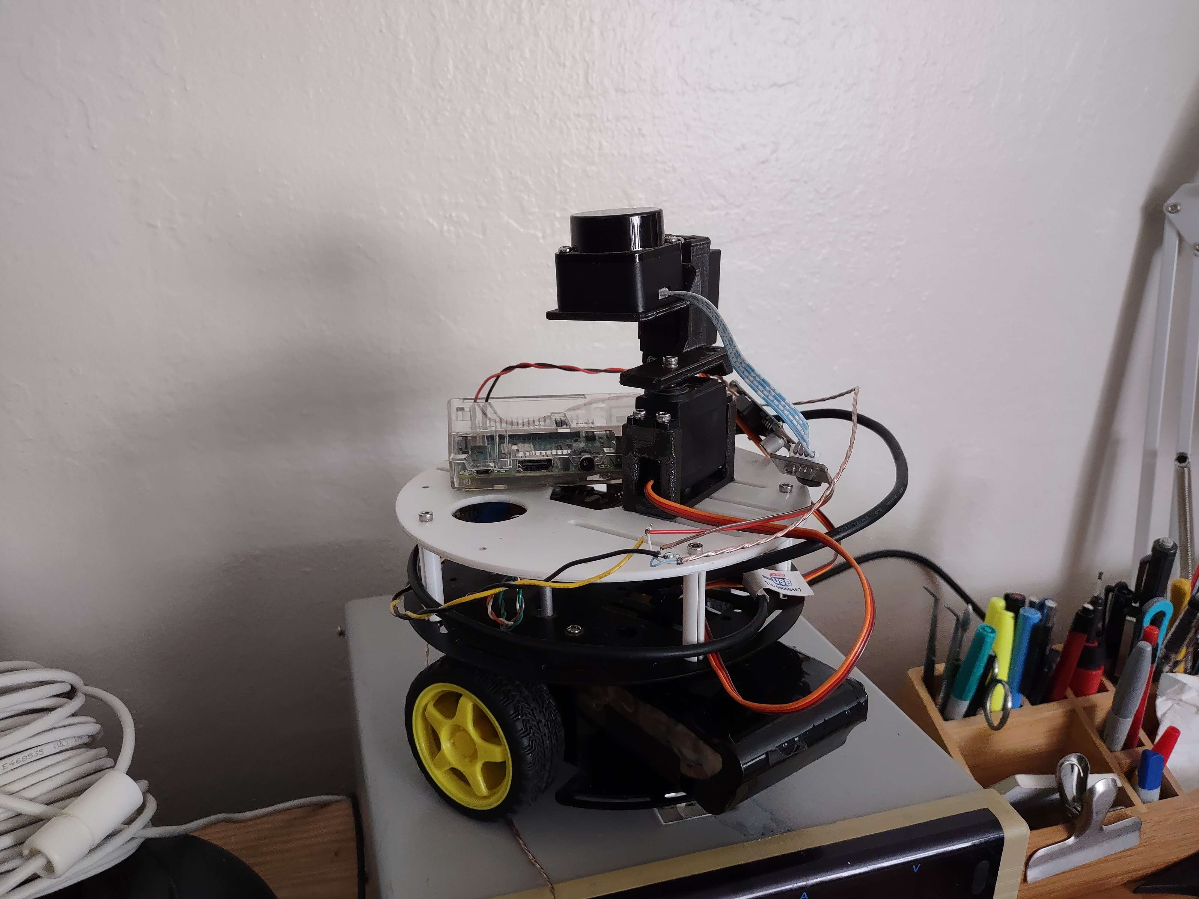
- Servos with pan-tilt to aim the LIDAR and cameras
Software:
- Arduino sketch for the Romeo board
- Control program for the Raspberry Pi
- Dashboard and server program for the AI workstation
- SLAM for navigation
- Point cloud collection for mesh reconstruction offline
- Multi-modal AI agent to control the robot
Unsurprisingly, half the motivation behind this project is to use my VulcanAI project to allow a self-hosted agentic AI to control the robot, but that will require a lot of infrastructure first.
Firmware
The first step was to get the Romeo board up and running to control the rover’s motors and eventually the servos too. I had played with this chassis and board in college, so I knew it was pretty simple to get working, but I was curious how well AI would handle the task. I fed the Arduino and Romeo documentation to Cursor and gave it a thorough description of what I needed. To summarize, I wanted it to accept commands over UART and decode them to set the motors and servos. Cursor generated some very straightforward Arduino code that did exactly what I needed. Not micro-optimized or terse, but not spaghetti code either. Considering Arduino was designed for students, hobbyists, and rapid prototyping, I am not surprised but still pleased with how well it worked. For something so simple and tedious, it is nice to offload the boilerplate to automation.
Software
Next came the code for the Raspberry Pi. I wanted the software to be cross-platform and run equally well on my Windows workstation, Linux laptop, and Raspberry Pi. Since the more elaborate sensors like LIDAR and cameras are all USB, it is convenient to test them directly on the system I am coding on. I could do this with C++, Python, or any number of other languages and platforms, but my favorite golden hammer is still C#, especially as .NET has evolved to be an excellent cross-platform solution even on low-power SoCs like the anemic Raspberry Pi 3 I am using.
Microcontroller Interface
Since this is a bottom-up sort of project, the software began with a class to interact with the Romeo board, sending it commands and reading back telemetry. Talking to a microcontroller over UART from C# is something I’ve done a million times already, so I decided to offload it to Cursor again. I wrote out the class skeleton with the public methods I required, then gave the AI agent a paragraph describing what the class should do and a reminder that it needed to be cross-platform between Linux and Windows. From experience, I know that serial ports on Windows and Linux differ significantly, even with the .NET API abstracting much of the complexity. I was pleased when the AI’s code intelligently checked if the platform was Linux-based and searched the /dev directory for variants of /dev/ttyACM and /dev/ttyUSB—something I vividly recall dealing with in both C# and Python years ago and had no desire to fuss with again. Overall, the rest of the class was pretty straightforward, partially because Cursor had access to the Arduino sketch for reference.
At this point, I am just getting greedy, because the most annoying part of USB COM ports is figuring out what the device will be named, since it will be named differently on everything I plug it into. I asked Cursor to add some logic to automate this, and in a single step it added a query/response to the Arduino sketch and added a method to query all the USB serial ports and check for the response. Not a very novel solution, but a reliable one that works well enough.
LIDAR Interface
This is where I put my Software Architect hat on. I know from the start that I will be using a 2D LIDAR module, but I have goals of using the 2D LIDAR to collect 3D LIDAR data, as well as more distant goals of using a 3D depth camera, 1D distance sensors, and a 3D RADAR module I recently received. Most importantly, I want to be able to pool all of this data for 2D and 3D mapping and autonomous navigation. With only 2D LIDAR on the immediate agenda but so many possibilities to explore later, I wanted to keep the software modular so I defined an ISensor2D interface. It allows a sensor object to have angular and linear offsets relative to the robot, and it outputs one or more 2D points of detected obstacles relative to the robot’s position on a 2D plane aligned with the robot. For future expansion to 3D data, I will add an interface like ISensor3D and have a simple wrapper that takes an ISensor2D as well as a 3D rotation and offset to translate 2D points into 3D. This will be essential when I try using the 2D LIDAR for 3D scanning by moving it on a pan/tilt assembly.
Again, the actual interaction with the LIDAR module is something I have done before in both Python and C#, and while my previous code wasn’t suitable for reuse in this project, it was a good basis to rewrite to the ISensor2D interface. And again, rewriting old code to a new interface isn’t something I was keen on spending much time on so I tasked Cursor with it. I fed it the LD06 datasheet, the wonderful write-up by James Gibbard, and the Python and C# I had written and debugged previously. Sure enough, the AI had no trouble rewriting my code to fit the new interface. As I reviewed the AI’s code (as you should always do with AI-generated content), I noticed a handful of small changes such as a thread-safe buffer for the data, and it even implemented decoding for a few fields in the LIDAR’s output that I had ignored. It simply followed the structure and format of my code and continued it according to the information in the datasheet. Fabulous.
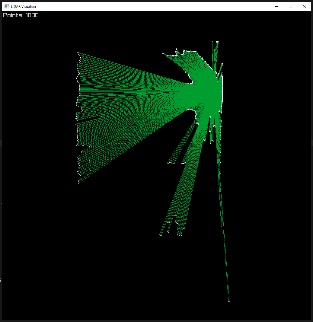
A bit of a surprise came when I asked Cursor to rewrite the Main method to demonstrate usage of the new LIDAR class, and it went so far as to implement an entire visualization using ASCII art. I had previously attempted the same thing when I first got the LIDAR module and wrote a C# class for it, but ran into a few bugs I didn’t have the time or energy to deal with. Running the program and seeing my workshop rendered in ASCII art was immensely satisfying.
Networking
Networking is a task I have wrestled with many times across multiple projects. In C# specifically, I have had mixed results with TCP but had recently had good results with the NetMQ library to simplify basic messaging between programs. I wasn’t sure if NetMQ would be fast enough for my needs, so I started with an INetworkConnector interface so that I could cleanly try different approaches without having any of them tightly coupled with the rest of the code. Again, I already had a working class using NetMQ in another project so I used it as the basis of the new interface and quickly ported it into the project. To make debugging simpler, I added a testing project and a class of test cases that accepted an INetworkConnector. After a rather annoying afternoon of debugging, I had reliable communication back and forth in the tests.
Out of curiosity, I defined a new class named TcpConnector and added it to the test suite, then asked Cursor to implement the class however it saw fit. What it produced was indeed a pure .NET implementation that used raw TCP sockets, and it did pass the tests, but reviewing the code revealed it had over-fit to the tests so that the TcpConnector objects would function as client or server depending on which port they were assigned and it couldn’t do true bidirectional communication. I expanded the test suite to reveal this limitation and asked Cursor to fix it. After a bit of back and forth, it had the class working as a true bidirectional TCP connector. Honestly, the interaction taught a couple good lessons for AI-generated code and software engineering in general. By providing the test cases, the AI was able to implement a lot of complex behavior with little effort, but the result was only as good as my tests and my own assumptions resulted in ambiguity that the AI exploited to allow simpler code.
Visualization
The AI-generated ASCII art visualization was a handy way to demo and debug the LIDAR, but it wasn’t very practical. With the software moved onto the Raspberry Pi, I needed a robust way of capturing log data and visualizing the LIDAR data on the workstation where the AI and other high-level logic was going to be. With the networking sorted out, I added the Dashboard program to the project. I had already built a custom Logging class to aggregate and filter event logging and debug messages, and it was no trouble to have the software’s main loop serialize those messages to JSON and shoot them over to the dashboard so the dashboard could display them for me.
With text-based data reliably flowing, I needed to pass the 2D LIDAR points from the Raspberry Pi to the Dashboard. The trivial solution was to serialize it to JSON as well, but size limits for both NetMQ and TCP became an issue. I could have modified the network code to handle much larger messages, but that would just kick the issue down the road. I was still serializing a large amount of simple numerical data into text and then deserializing it on the other end, consuming CPU time and network bandwidth. Instead, I modified the INetworkConnector interface to include an optional byte[] alongside a string for each message. Testing with even 8192 2D points, I could fit all the data in a single packet. I updated the TcpConnector myself since that was the class I was using at this point, but I had Cursor update the NetMQConnector class as well and ensured it passed the tests and could still be used interchangeably.
With the 2D points getting streamed to the dashboard, the next step was visualizing them, which was fairly trivial. For quick and dirty graphics, Raylib is my tool of choice in pretty much every platform, while the Raylib-CS bindings provide the most convenient way of using it from .NET while still being cross-platform. The drawing was simple: For each 2D point, apply a scale and offset and draw a line from the point to the center, and then a small “x” at the point. Repeat every frame using the latest batch of points.
Remote Control
The goal is to have a robot that is fully autonomous, but since the high-level logic will be on a stationary PC, it still needs to be controllable over the network. Since the network connector already provided bidirectional communication, all I needed was to send commands to set the speed and direction of each motor. I had already mapped the arrow keys to pan the LIDAR visualization, so I mapped the WASD keys and used RayLib again to detect the key presses and then send the commands over the network connector.
Next Steps
There is a lot to be done on the Mite, still. Up to this point, the project has largely been piecing together things I have done before and making some refinements so they work together and will be maintainable going forward. Currently, the whole system is powered by a long wire connected to a benchtop PSU, so the next step is to add a battery.
The LIDAR module itself is mounted on a pan/tilt assembly with the plan of holding it horizontally for real-time navigation and tilting it to rotate the scanning plane to measure a cylinder around the robot. This is a further goal, and for now the LIDAR interface is not performing as hoped. The points being collected are decoded with a latency of over a second, and it takes several seconds of scanning to get a decent measurement of the area. This makes it difficult to use for real-time navigation, and I worry it won’t be suitable for SLAM. I am also fairly certain this will be an issue for 3D scanning, since I would need to hold each angle for several seconds before proceeding.
And of course, that old 2WD chassis has its own problems, with one of the motors not turning very freely so rolling in a straight line is unreliable. I recently obtained a dead robot vacuum cleaner and with the electronics removed the chassis and motors will be a perfect replacement.